Hello again, I will continue my ray tracing adventure with Part 4, focusing on implementing features:
- Texture Mapping
- Normal and Bump Mapping
- Diffuse and Specular Maps
- Perlin Noise
- Checkerboard Patterns
Before I begin, I should mention that this blog and project are part of the Advanced Ray Tracing course given by my professor Ahmet Oğuz Akyüz, at Middle East Technical University.
Bugs from Previous Parts
As I mentioned in previous sections, my renders were showing excessive reflections, making the scene appear more reflective than it actually was. I easily found the source of the problem by referring to a blog post where Oğuz hoca answered. I was applying reflection directly if any coordinate value of the material’s mirror reflectance vector was greater than 0, but it turned out that mirror reflectance should only be applied if the material’s _type value is ‘mirror’. As Oğuz Hoca indicated, checking via _type solved the problem, and the renders were the same as expected.
// else if (material.mirrorReflectance.x > 0 || material.mirrorReflectance.y > 0 || material.mirrorReflectance.z > 0)
else if (material.type == "mirror")
Texture Mapping
Texture mapping is a fundamental technique in computer graphics used to add surface detail to 3D models. Instead of assigning a single flat color to an object, we map a 2D image (or a procedural pattern) onto the 3D surface using UV coordinates. This allows us to simulate complex materials like wood, stone, or earth without increasing the geometric complexity of the mesh. This technique is widely used in video games because it gives good looking results without requiring high processing power by keeping the geometry simple, even though the textures can be very detailed.
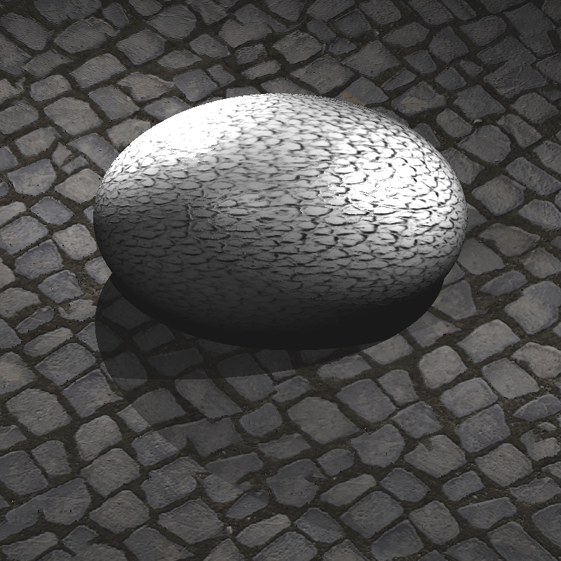
There are two main types of texture mapping I implemented: Image Textures and Procedural Textures. Image textures use images like PNG to define surface colors, while procedural textures generate patterns algorithmically (like Perlin Noise for some patterns, as in sphere_perlin_bump render).
Also, there are different types of texture maps that serve various purposes. Normal Maps and Bump Maps modify surface normals to simulate detail, while Diffuse and Specular Maps define how light interacts with the surface. These maps usually look like this:
Normal Map Example from Homework Inputs
Diffuse and Specular Map Examples from Homework Inputs
We map textures using UV coordinates, which are 2D coordinates that correspond to points on the texture image. The U coordinate typically runs horizontally across the texture, while the V coordinate runs vertically. These coordinates are normalized between 0 and 1, and they are assigned to each vertex of the 3D model. During rendering, the UV coordinates are interpolated across the surface of the polygon to determine which part of the texture image corresponds to each pixel on the screen.
But choosing which texel (texture element) to sample is crucial for quality. Many games or game engines ask the user for different sampling methods to avoid artifacts like aliasing or blurriness. For example, in Unity, you can choose which method to use for texture filtering.
Unity Filtering Options
There are several sampling techniques, but I focused on two primary methods: Nearest Neighbor and Bilinear Interpolation.
Nearest Neighbor
The Nearest Neighbor method is the simplest way to sample a texture. It involves rounding the U and V coordinates to the nearest integer pixel in the texture image. This method is fast and easy to implement, but it can lead to noticeable artifacts, especially when the texture is viewed up close or at steep angles. The result can appear blocky or pixelated because it doesn’t consider any neighboring texels.
I implemented Nearest Neighbor sampling as follows:
Vec3 Image::sampleNearest(const Vec2& uv) const {
    if (width <= 0 || height <= 0 || pixels.empty()) return Vec3(0,0,0);

    // Clamp [0,1]
    float u = clamp01(uv.u);
    float v = clamp01(uv.v);

    v = 1.0f - v; // Flip V coordinate for image origin at top-left

    // Find nearest texel (pixel center)
    int x = (int) std::floor(u * (width - 1) + 0.5f);
    int y = (int) std::floor(v * (height - 1) + 0.5f);

    // Clamp to image boundaries
    x = std::max(0, std::min(width - 1, x));
    y = std::max(0, std::min(height - 1, y));

    // Get pixel color
    int idx = (y * width + x) * channels;
    float r = pixels[idx + 0] / 255.0f;
    float g = pixels[idx + 1] / 255.0f;
    float b = pixels[idx + 2] / 255.0f;

    return Vec3(r, g, b);
}
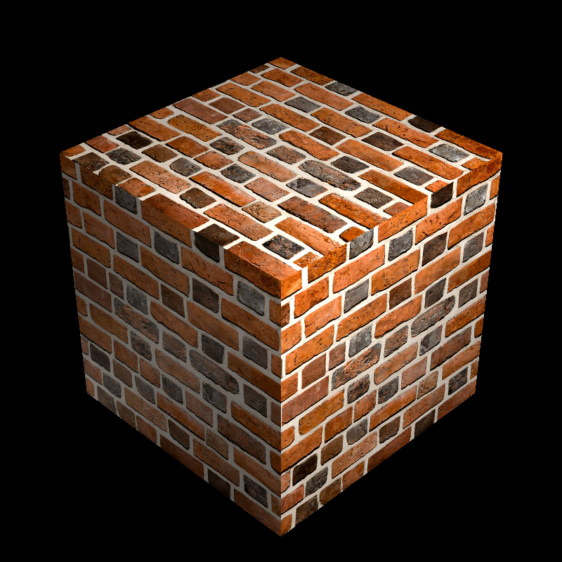
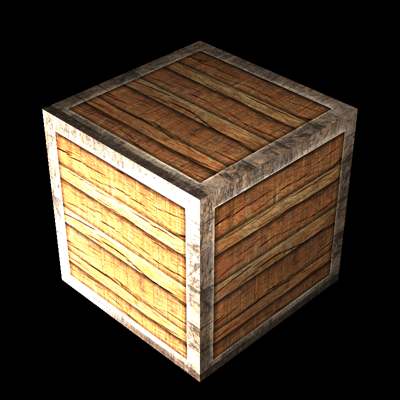
When I run this, I see a render like this, and I thought that it was the same as the expected result at first glance.
Bugged Cube Wall Normal
Then, after some time, I also wanted to test my results with a comparison tool, and I found out that my implementation was slightly off.
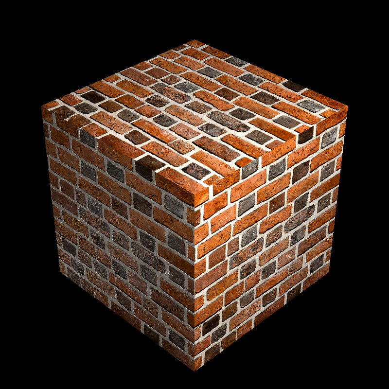
Upon closer inspection, I realized that the problem was a simple assumption I made about where the “starting point” of the image was. I assumed that the texture coordinates (0,0) should start at the top-left corner of the image. To match this assumption, I added the line v = 1.0f - v; to flip the vertical coordinate upside down.
It turned out my assumption was wrong. The input data was already set up correctly, so by flipping the V coordinate, I was actually breaking the alignment by inverting it unnecessarily. So I removed that line and got the correct results.
Even though this method is simple to implement and solves the problem, for image textures, simply picking the nearest pixel can result in “blocky” artifacts when the camera is close to the surface.
Bilinear Interpolation
To improve this, we can use Bilinear Interpolation. In this method, instead of taking the single nearest texel, we sample the four surrounding texels and interpolate their colors based on the exact UV position.
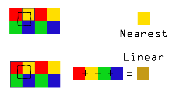
Nearest Neighbor - Bilinear Comparison from gamedevelopment.blog/texture-filter
Here is how I calculated the weighted average of the four neighbors:
// Bilinear interpolation of four neighboring texels
Vec3 top = c00.scale(1.0f - dx).add(c10.scale(dx));
Vec3 bot = c01.scale(1.0f - dx).add(c11.scale(dx));

Vec3 color = top.scale(1.0f - dy).add(bot.scale(dy));
Here, c00, c10, c01, and c11 are the four nearest texels, while dx and dy represent the fractional offset inside the pixel cell. Interpolation is first done along the x-axis, then along the y-axis.
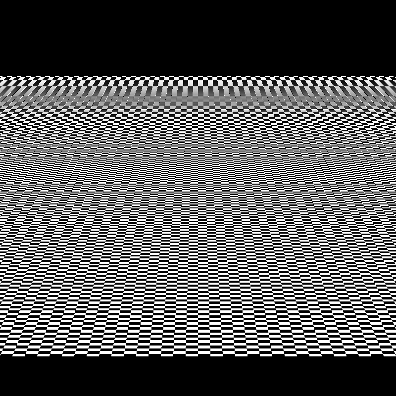
We can also see the difference in my renders between Nearest Neighbor and Bilinear Interpolation in the plane_nearest and plane_bilinear renders.
plane_nearest vs plane_bilinear
There are more advanced techniques like Mipmapping and Anisotropic Filtering, but for this project, Nearest Neighbor and Bilinear Interpolation were sufficient for me to achieve good quality textures.
Bump Mapping
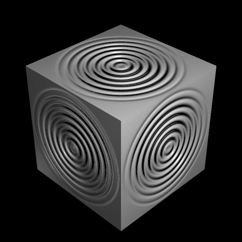
While texture mapping changes the color, Bump Mapping changes the surface normal used in lighting calculations to simulate depth and wrinkles. It works by perturbing the surface normal based on the intensity (or height) of a texture map. This creates the illusion of geometric detail, like the ridges on a spaceship, without actually moving any vertices.
I sample the height at (u, v) and at two nearby points (u + du, v) and (u, v + dv). Here, du and dv are chosen as one texel step (1/width, 1/height). The differences hx and hy approximate the slope of the height field in U and V directions.
Also, if a normal map (ReplaceNormal) exists, I skip bump mapping to avoid stacking two normal modifications on top of each other.
// Height from texture (grayscale)
float du = 1.0f / bumpTM->image->width;
float dv = 1.0f / bumpTM->image->height;

float h  = H(u, v);
float hx = H(u + du, v) - h;
float hy = H(u, v + dv) - h;

// Scale effect
hx *= bumpTM->bumpFactor;
hy *= bumpTM->bumpFactor;

// Tangent-space perturbed normal
Vec3 nTS(-hx, -hy, 1.0f);
nTS = nTS.normalize();

Vec3 nW = T.scale(nTS.x).add(B.scale(nTS.y)).add(N.scale(nTS.z)).normalize();
hitNormal = (nW.dot(rayDir) > 0.0f) ? nW.scale(-1.0f) : nW;
In the code snippet above, you might have noticed the bumpFactor variable. This is an important parameter because the raw intensity values from a texture image (0 to 255) do not have a physical height. Without a scaling factor, the calculated gradients might be too steep or too shallow for the object’s scale. While a high value creates sharp ridges, making the surface look very rough, a low value creates subtle imperfections, like the grain on wood.
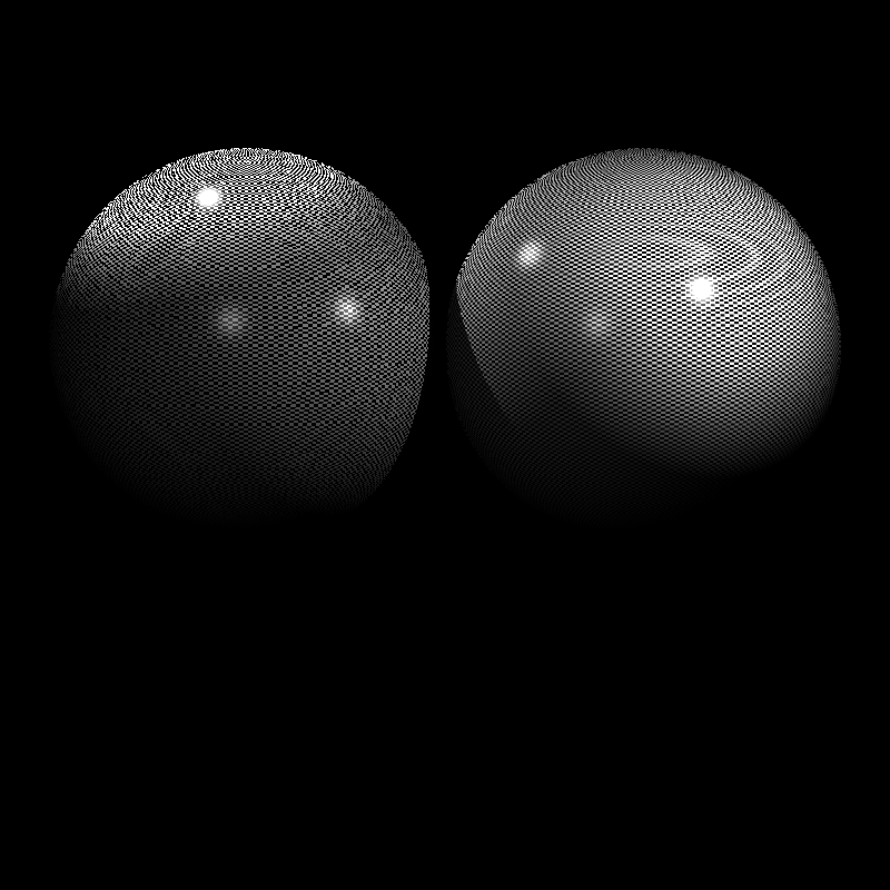
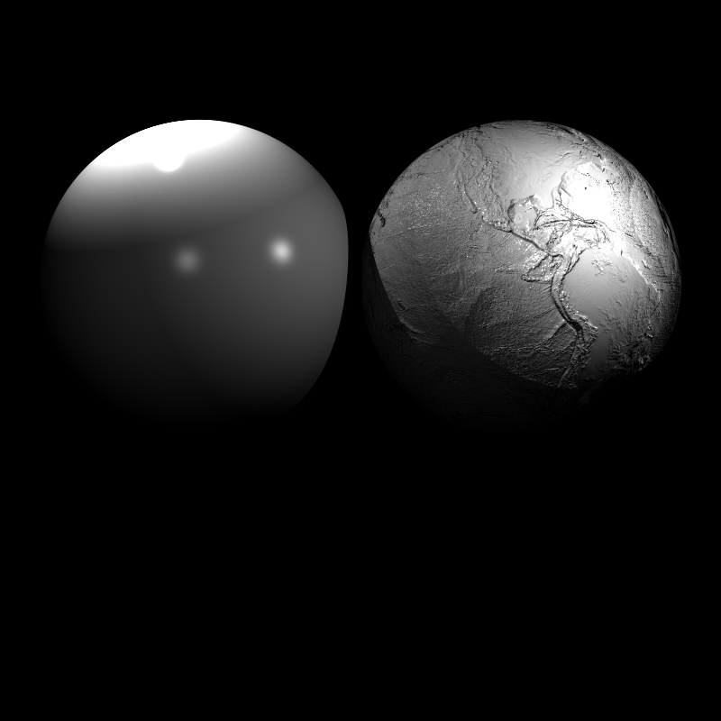
Not all scenes included a bump factor value, so I used 0.01f as a default value for those scenes. Here you can see some different bump factor values and their effects on the final render.
0.01, 1, and 10 Bump Factors from Left to Right
Diffuse & Specular Reflectance Mapping
While Bump Mapping handles the geometry’s “feel,” Diffuse Mapping handles its “look.” This is the most common form of texturing, where an image is mapped onto the 3D surface to define its color.
In my shading loop, image textures can modify material reflectance directly. Depending on DecalMode, the sampled texture color is used to replace or blend the diffuse term (kd), replace the specular term (ks), or, in ReplaceAll mode, bypass lighting entirely. I sample the texture using nearest or bilinear filtering and apply the optional normalizer scaling before updating the coefficients.
Vec3 texColor;
if (tm->interpolation == InterpolationMode::Bilinear) {
    texColor = tm->image->sampleBilinear(info.hitUV);
} else {
    texColor = tm->image->sampleNearest(info.hitUV);
}

if (tm->normalizer > 0.0f && tm->normalizer != 255.0f && tm->normalizer != 1.0f) {
    float scaleFactor = 255.0f / tm->normalizer;
    texColor = texColor.scale(scaleFactor);
}

if (tm->decalMode == DecalMode::ReplaceKd) kd = texColor;

else if (tm->decalMode == DecalMode::BlendKd) {
    // Blend with existing kd
    kd = kd.add(texColor).scale(0.5f);
}

if (tm->decalMode == DecalMode::ReplaceKs) ks = texColor;

if (tm->decalMode == DecalMode::ReplaceAll) {
    doReplaceAll = true;
    replaceAllColor = texColor;
}

//...

// Return immediately if ReplaceAll was applied
if (doReplaceAll)
    return replaceAllColor.scale(255.0f);
By modifying kd and ks before the lighting calculation, the rest of the ray tracer (shadows, light attenuation, etc.) works automatically with these new, detailed material properties.
Checkerboard Textures
One of the simplest and most useful procedural textures is the 3D checkerboard. Instead of sampling an image using UV coordinates, we compute the color directly from the hit point position. This gives a pattern that has no texture resolution limit, and it’s especially useful for debugging mapping.
My implementation follows the pseudo-code shared with the homework.
static Vec3 sampleCheckerboard(const CheckerTextureMap& tm, const Vec3& pos)
{
    bool x = ((int)std::floor((pos.x + tm.offset) * tm.scale)) % 2;
    bool y = ((int)std::floor((pos.y + tm.offset) * tm.scale)) % 2;
    bool z = ((int)std::floor((pos.z + tm.offset) * tm.scale)) % 2;

    bool xorXY = (x != y);
    if (xorXY != z) return tm.blackColor;
    else return tm.whiteColor;
}
But there is an important detail, if we sample the checkerboard in world space, then moving an object might make the pattern look like it’s “stuck to the world” rather than painted on the object. To make the checkerboard behave like an actual object texture, I transform the hit point into the object’s local space using the inverse model matrix.
// Transform hit point to object local space
glm::mat4 invM = glm::inverse(info.modelMatrix);
glm::vec4 pL = invM * glm::vec4(hitPoint.x, hitPoint.y, hitPoint.z, 1.0f);
posForProc = Vec3(pL.x, pL.y, pL.z); // Use this position for procedural texture sampling

Vec3 texColor = sampleCheckerboard(*tm, posForProc);
Perlin Noise
Finally, I implemented the most popular procedural texture technique, Perlin Noise. Unlike images, procedural textures are calculated on the fly using mathematical functions. Perlin Noise is a gradient noise function that produces smooth, natural-looking patterns. It is widely used for simulating organic textures like clouds, marble, wood grain, and terrain. Because of the easiness and amazing results of Perlin Noise, Ken Perlin even won an Academy Award for Technical Achievement for his invention in 1997.
The video “What is Perlin Noise?” by Acerola about the Perlin Noise was very fun and informative to watch. It helped me to understand the concept better. I strongly recommend it to anyone interested.
Perlin Noise works by defining a grid of random gradient vectors and interpolating between them based on the input coordinates. This creates a continuous noise function that can be sampled at any point in 3D space.
I used an existing implementation of Perlin Noise from here and integrated it into my ray tracer.
In practice, Perlin Noise is often combined across multiple octaves to create fractal patterns. Each octave increases the frequency while decreasing the amplitude, allowing both large scale structure and detail to appear simultaneously.
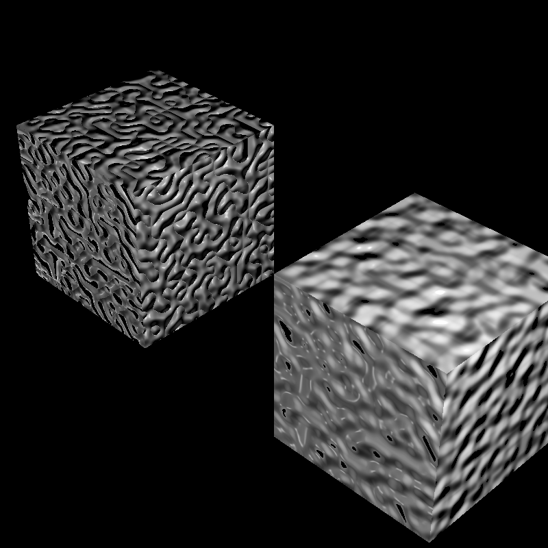
I implemented support for turbulence, which is created by taking the absolute value of the noise before accumulation. This folds the noise around zero and produces sharp, marble-like or snake-like veins:
for (int k = 0; k < K; ++k) {
    Vec3 q = p.scale(freq);
    float n = gPerlin.noise(q.x, q.y, q.z);

    if (tm.conversion == NoiseConversion::AbsVal) {
        s += amp * std::fabs(n);
    } else {
        s += amp * n;
    }

    ampSum += amp;
    freq *= 2.0f;
    amp *= 0.5f;
}
Normalizer
There is also a field named “Normalizer” in the input files for some textures. I interpreted this as a divisor for the standard 8-bit color range, applying a scaling factor of 255.0f / Normalizer.
if (tm->normalizer != 255.0f && tm->normalizer > 0.0f) {
    float scaleFactor = 255.0f / tm->normalizer;
    texColor = texColor.scale(scaleFactor);
}
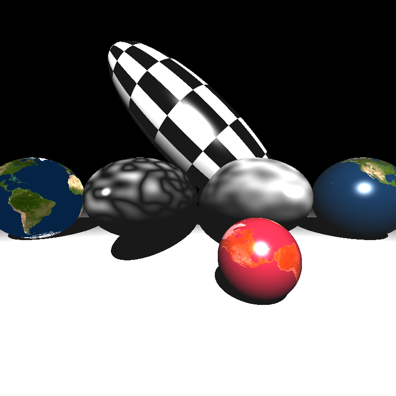
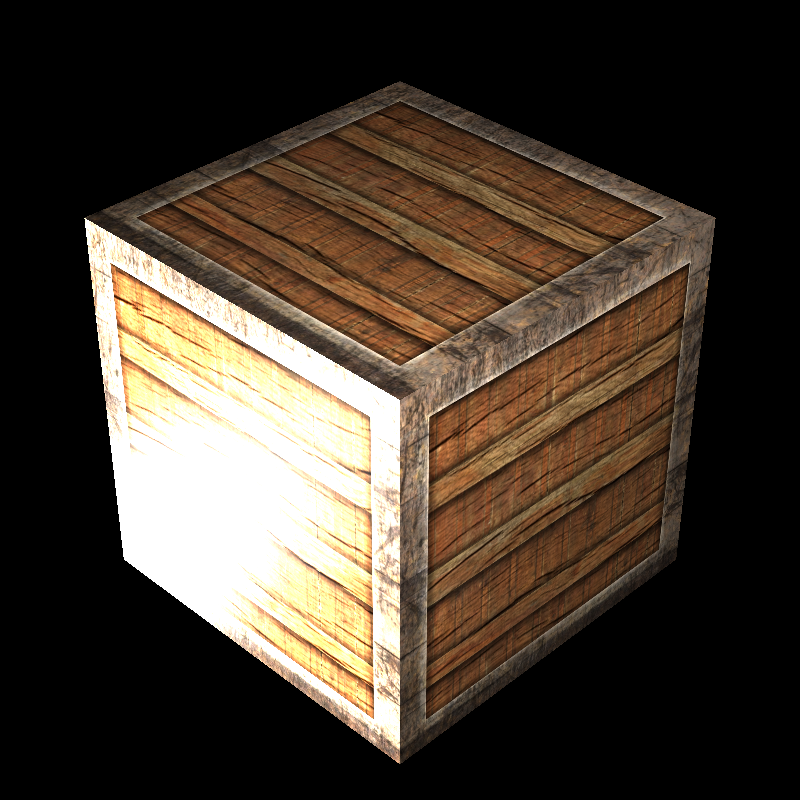
But after trying this on ellipsoids_texture scene, I realized that something is wrong. Also, at this time, I was trying to figure out why the painting on the wall is completely white in the veachajar scene.
When I checked the Normalizer value in the ellipsoids_texture scene, it was set to 1.0f, which means no scaling should be applied. However, I mistakenly applied the scaling factor regardless of the Normalizer value, thus multiplying the texture colors by 255.0f, leading to completely white colors. So I also checked for the 1f value and skipped scaling in that case, which fixed the problem.
if (tm->normalizer > 0.0f && tm->normalizer != 255.0f && tm->normalizer != 1.0f) {
    float scaleFactor = 255.0f / tm->normalizer;
    texColor = texColor.scale(scaleFactor);
}
Outputs and Closing Thoughts
Even though this part was including straightforward implementations of well-known techniques, testing the features and debugging them took a lot of time because wrong texture mapping results cannot be easily diagnosed by human eyes, as in my bug in the nearest neighbor section.
Therefore, I used digital tools a lot for debugging, such as Diffchecker.
Sphere inputs did not include the bump factor value, so I tried different values to see which one is giving the expected results and used 10 as the bump factor for those scenes. Also, in veachajar scene, I got a PLY read error while importing the models/Mesh015_fixed.ply file, but when I used the original models/Mesh015.ply file, it worked fine. The happly library was giving an error about unsigned int usage in the fixed file, so I just used the original file.
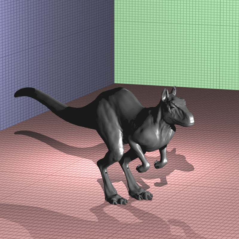
Other than these, I get somewhat different results in killeroo_bump_walls scene. I could not figure out the exact reason, but I thought it might be related to the bump factor but even different bump factor values did not result in an exact match with the expected output. I will investigate this issue further in the next parts.
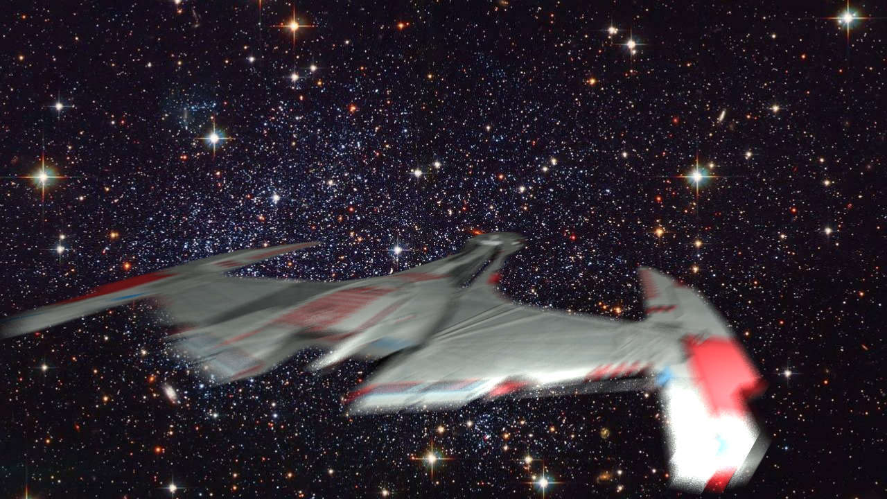
Before wrapping up this part, I would like to share a render that genuinely made me laugh. At that point, I had forgotten to apply the vertex and texture offsets and hadn’t fixed the reflectance bug yet, so this is what I ended up with while testing the galactica_static scene:
As in previous parts, I would like to thank Professor Ahmet Oğuz Akyüz for all the course materials and guidance, and Ramazan Tokay for contributions to the 3D models. Here are my final renders and their render times:
| Scene | Time (seconds) |
|---|---|
| brickwall_with_normalmap | 1.60214 |
| bump_mapping_transformed | 3.24855 |
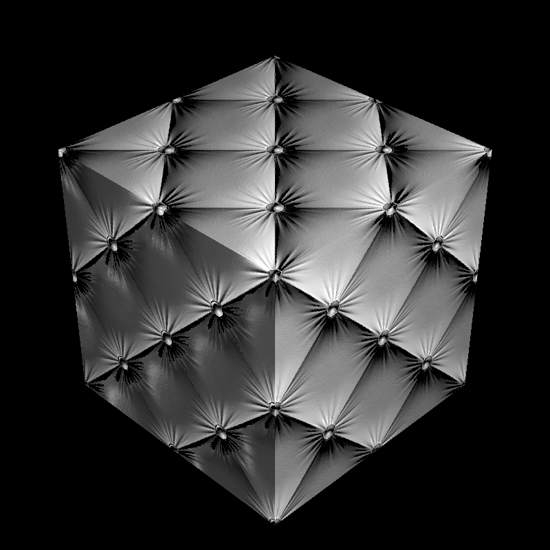
| cube_cushion | 1.53794 |
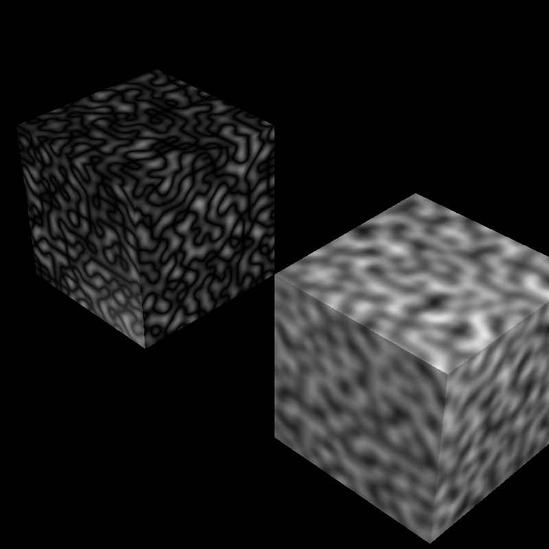
| cube_perlin | 1.47713 |
| cube_perlin_bump | 1.56417 |
| cube_wall | 1.57439 |
| cube_wall_normal | 1.566830 |
| cube_waves | 1.63458 |
| ellipsoids_texture | 2.92964 |
| galactica_dynamic | 449.681 |
| galactica_static | 5.75577 |
| killeroo_bump_walls | 26.6139 |
| plane_bilinear | 1.09835 |
| plane_nearest | 1.13796 |
| sphere_nearest_bilinear | 2.16499 |
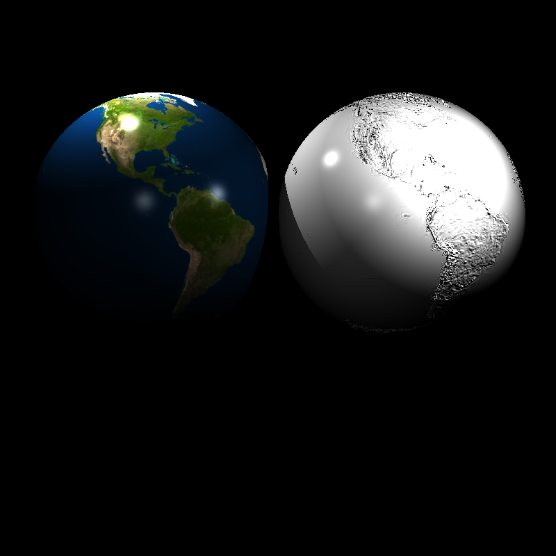
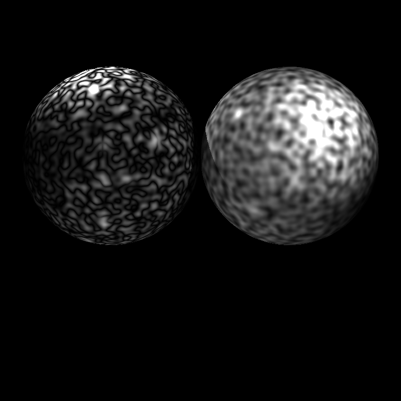
| sphere_nobump_bump | 1.9995 |
| sphere_nobump_justbump | 1.94817 |
| sphere_normal | 117.432 |
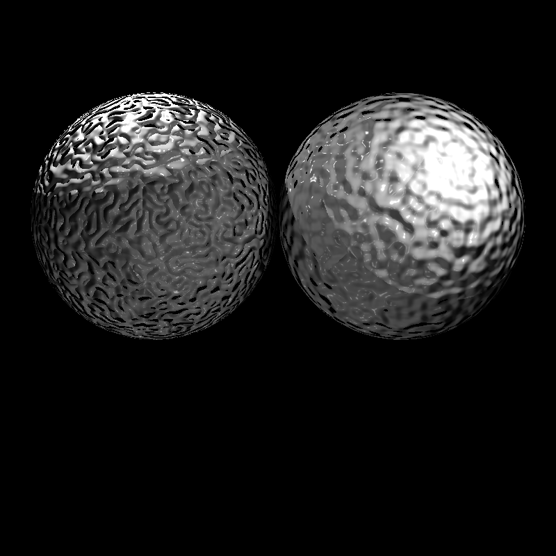
| sphere_perlin | 2.4421 |
| sphere_perlin_bump | 2.55343 |
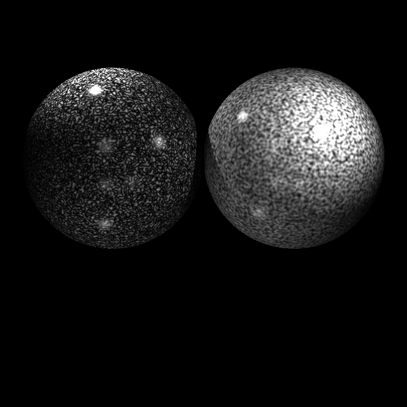
| sphere_perlin_scale | 2.40968 |
| wood_box | 1.58755 |
| wood_box_all | 1.60994 |
| wood_box_no_specular | 1.5577 |
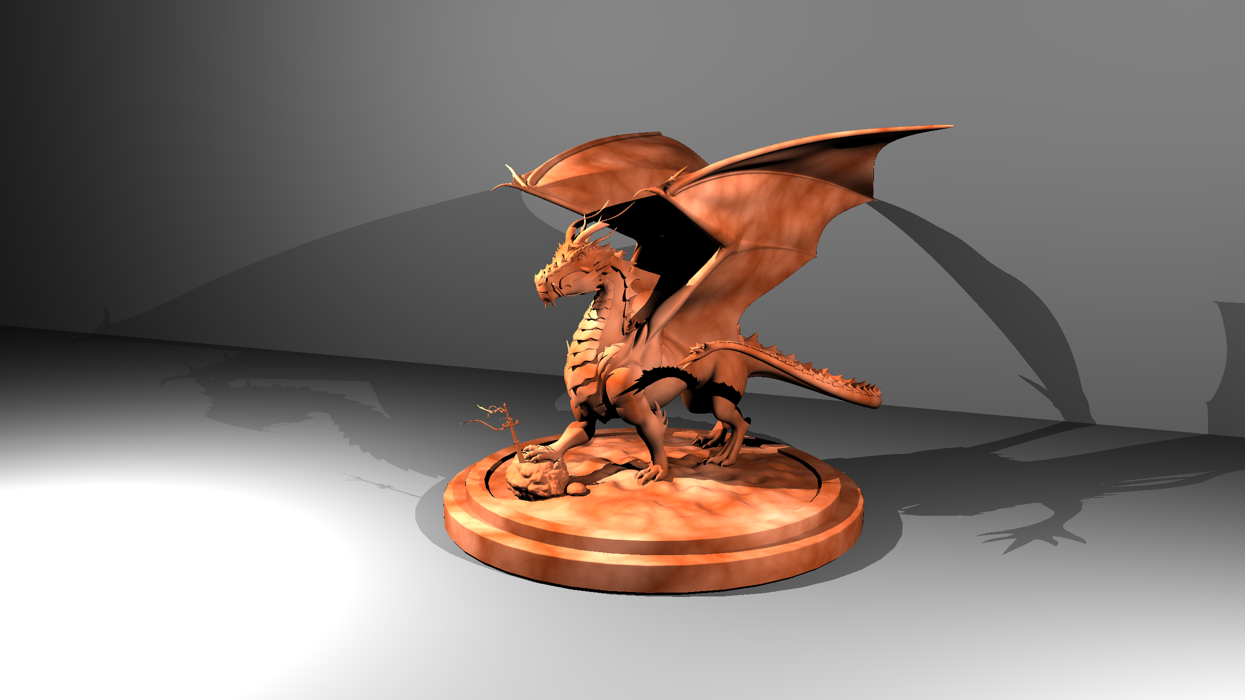
| dragon_new | 14394.7* (3.686.400 pixels vs. my ray tracer :)) |
| mytap_final | PLY Read Error |
| 1 frame of tunnel_of_doom (400x400 resolution to speed up) | (approximately) 14* |
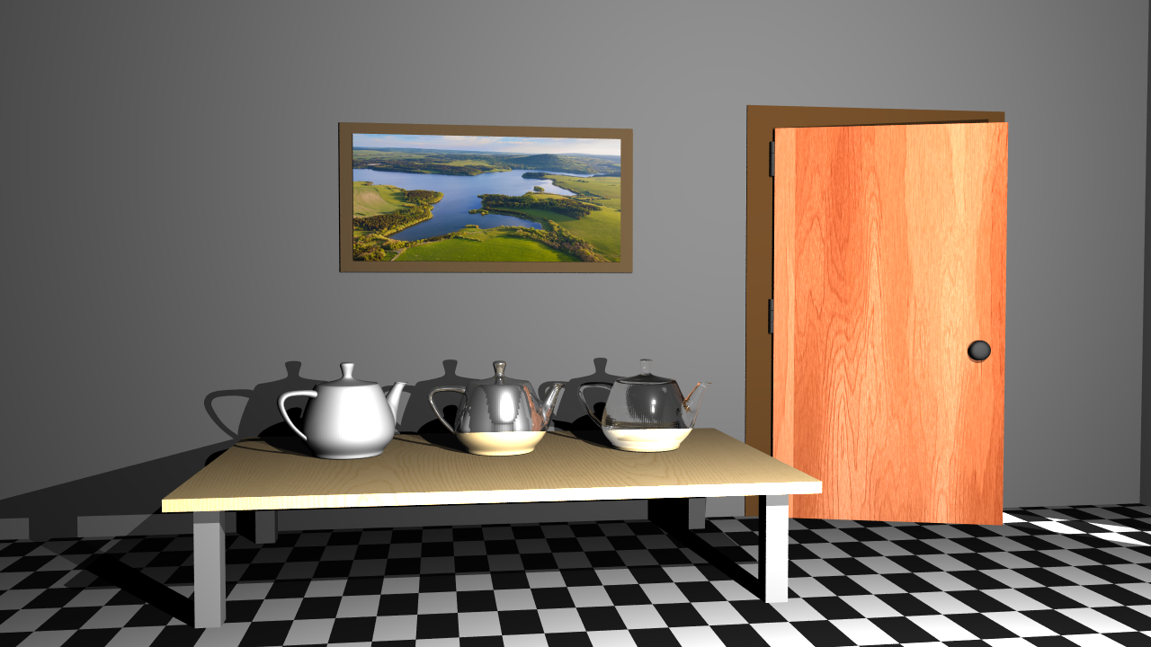
| VeachAjar | 174.211 |
Used CPU: AMD Ryzen 5 5600X 6-Core Processor (3.70 GHz)
*Used CPU: AMD Ryzen 5 7640HS 6-Core Processor (4.30 GHz)
dragon_new
This render took nearly 4 hours, and when I was losing my faith, my ray tracer finally won its battle with 3.686.400 pixels :). So I wanted to place this render at the top of all other renders.
Time: 14394.7 s
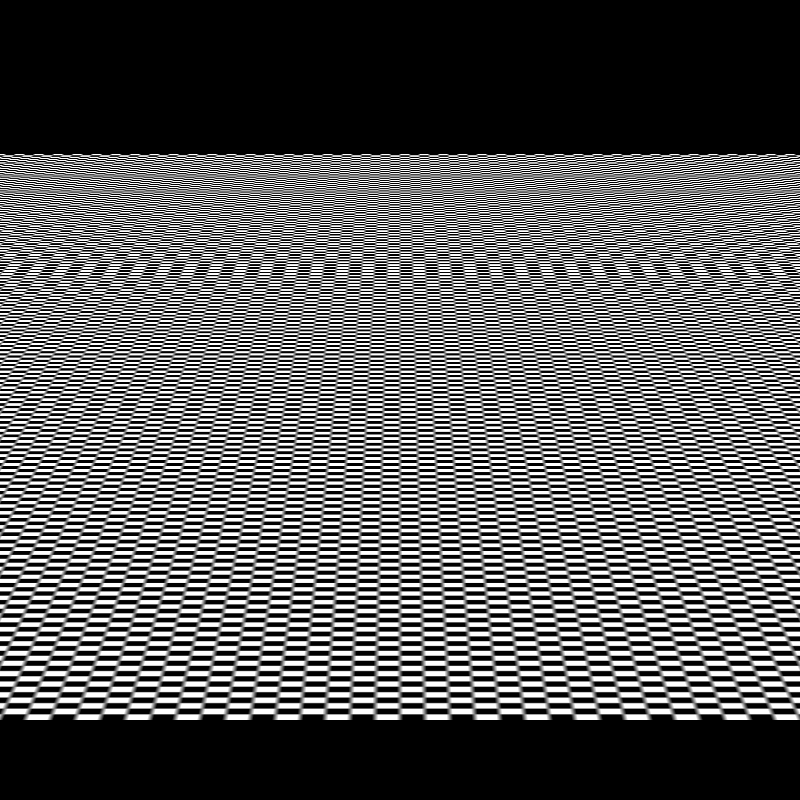
tunnel_of_doom
brickwall_with_normalmap
Time: 1.60214 s
bump_mapping_transformed
Time: 3.24855 s
cube_cushion
Time: 1.53794 s
cube_perlin
Time: 1.47713 s
cube_perlin_bump
Time: 1.56417 s
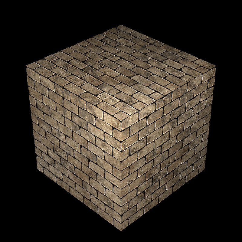
cube_wall
Time: 1.57439 s
cube_wall_normal
Time: 1.566830 s
cube_waves
Time: 1.63458 s
ellipsoids_texture
Time: 2.92964 s
galactica_dynamic
Time: 449.681 s
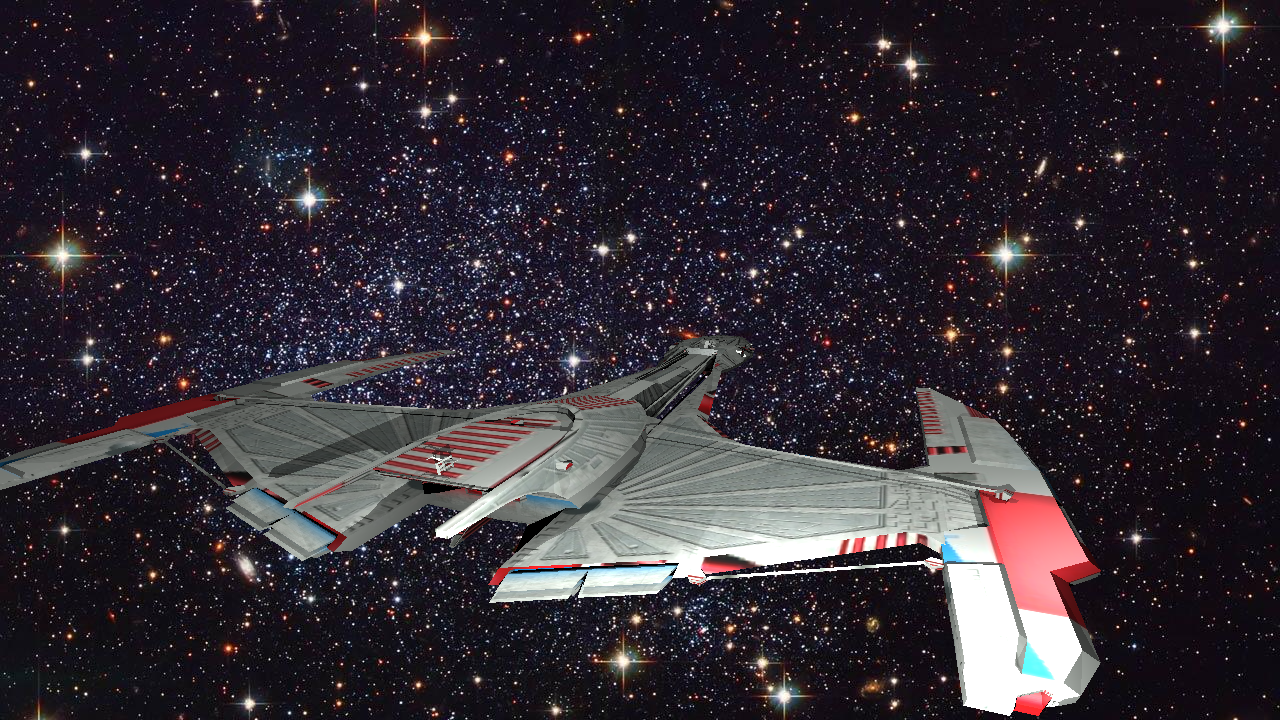
galactica_static
Time: 5.75577 s
killeroo_bump_walls
Time: 26.6139 s
plane_bilinear
Time: 1.09835 s
plane_nearest
Time: 1.13796 s
sphere_nearest_bilinear
Time: 2.16499 s
sphere_nobump_bump
Time: 1.9995 s
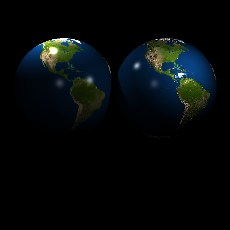
sphere_nobump_justbump
Time: 1.94817 s
sphere_normal
Time: 117.432 s
sphere_perlin
Time: 2.4421 s
sphere_perlin_bump
Time: 2.55343 s
sphere_perlin_scale
Time: 2.40968 s
wood_box
Time: 1.58755 s

wood_box_all
Time: 1.60994 s
wood_box_no_specular
Time: 1.5577 s
VeachAjar
Time: 174.211 s